Designing a Mobile Robot for Indoor Transportation: Common Hardware and Software Challenges

Example mobile robot with callouts showing IMU, LIDAR, Bumper, wheel encoders and onboard processor

Creating a mobile robot for indoor transportation is for sure a challenging task, especially when it comes to overcoming hardware and software issues. From choosing the right wheel-motor configuration and sensor set, to figuring out the best way to program the robot, it can be a daunting prospect. This guide will provide a high level overview of the various hardware and software challenges involved in creating a mobile robot, as well as the best solutions for overcoming them. With the right knowledge and preparation, you can create a mobile robot that is ideal for indoor transportation.

Understanding the Hardware Components for a Mobile Robot

To create a mobile robot, you will need to select the right hardware components. There are many components that make up a mobile robot, but in all cases it has:

  • The chassis which holds the wheels (or tracks) and drive train of the robot in place and serves as the mount point for all other parts;
  • An Onboard Controller, which serves as the brain of the robot, responsible for relaying information between sensors and actuators and the robot control software;
  • Sensors - This is the hardware used for navigation and safety, such as a camera, LIDAR, or collision sensors;
  • Motors and encoders for driving and steering, typically in a differential drive configuration;
  • Extra Actuators - These are the hardware components responsible for interaction with the carried goods.

Selecting the Wheel Configuration

One of the first challenges you will face when creating a mobile robot is selecting the right wheel configuration. Selecting the right wheel configuration will depend on the environment, application, and usage pattern of the robot. We’re excluding tracks here since we focus on indoor robots and tracks are used for muddy environments.

For the wheeled robots, we divide them in two categories: 3-wheel and 4-wheel platforms, although for correctness’ sake, many 3-wheel configurations get a 4th wheel on the opposite side of the steering wheel for stability reasons. We will also leave out the 4-wheel Ackerman steering, which is how every car works but is rarely used for indoor mobile robots.

These are the main features of the different 3-wheel configurations:

  • Omnidirectional: every wheel is driven by a motor and the omniwheel can also move sideways. Usage: platforms that need to be able to move and rotate instantly in any direction.
  • Differential: two alligned wheels driven by a motor independently, controlling both rotation and translation. The third wheel follows passively by rotating as it is pulled in either direction. Usage: platforms with heavy payload that need to rotate around a (central) axis.
  • Omni-Steer: Has a steering wheel driven by a motor and it’s orientation is controlled by another motor. The two remaining wheels follow passively as they are pulled in either direction. Usage: platforms with light payload and minimal cost requirements
  • Tricycle: Same driven steering wheel as the Omni-Steer, but the two remaining passive wheels are now fixed in the ‘forward’ direction. Usage: platforms with light payload and minimal cost requirements
  • Two-Steer: There are two steering wheels, whose orientation is connected mechanically or electronically and which may turn at different speeds. The third wheel follows passively by rotating as it is pulled in either direction. Usage: Rarely, writing a good controller for this configuration is excruciating (nudge to the PR2).

For indoor robots, the Differential Drive is among the most popular ones, followed by the Tricycle. Each configuration has its limitations and require different kinematic models and motion controllers to drive the robot along the desired trajectory.

Selecting the Right Sensor Setup

If you are creating a mobile robot for autonomous navigation, you will want to select a sensor setup that provides absolute position information, similar to GPS. Absolute sensors provide a known position that can be directly related to a location in a map. Unfortunately, GPS can’t be used indoors, and the industry came up with several alternatives. There is a way to use a relative sensor, for example LIDAR, 2D or 3D cameras, and match the contours they measure with a prerecorded map created by the same sensor (scan-area matching). This technology is called SLAM - read more about SLAM in our related article on Cartographer and the very short intro to SLAM here.

In addition, these relative sensors, can be used for collision detection, allowing them to have a double function… more on that later.

All sensors, like LIDAR or Cameras, will be connected to an onboard computer using an IO system. Common systems are Beckhoff EtherCat, IOLink or otherwise direct connection to the motherboard of the controller.

Programming the Robot for Autonomous Navigation

Once you have selected the right sensors and motors, you will need to program the robot for autonomous navigation. Depending on production volume, mobile robots are equipped with an off-the-shelve boxed controller with standard software for low volume, up to a dedicated motion control stack for higher volume robots. Boxed controllers are more expensive and introduce a dependency or lock-in on the controller supplier, while dedication motion control stacks are cheaper per unit, but require an in-house expertise to maintain and extend it.

Finally, it is also important to consider the amount of processing power available. Mobile robots often have lower processing power compared to larger, stationary robots due to their batteries. You can reduce the amount of processing power needed by using lower-precision navigation, simplifying the sensor set, or using a GPU. Most mobile robots are programmed in C or C++, assisted with code generators to generate the decision logic, similar to PLCs or state diagrams.

Addressing Safety Concerns - Collisions

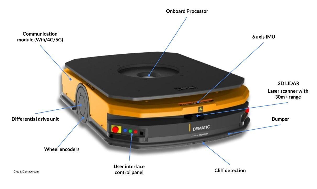
One of the most important considerations when creating a mobile robot is addressing safety concerns, particularly when it comes to collisions. For indoor mobile robots, you will want to select sensors that have a sufficiently long range and wide field of view. The three most common sensors used to avoid collisions are LIDAR, 3D cameras and Sonar, where the former is the most common with mid-size to large robots, the second for small to mid-size robots and the latter mainly serves to detect glass walls if they are present in that environment.

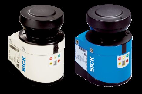
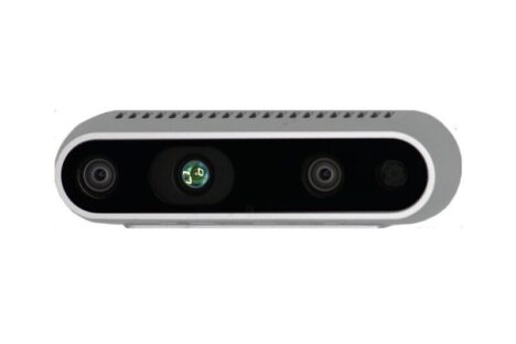
There is currently a fight going on between LIDAR and 3D cameras, the former led by traditional industrial sensor providers like Sick, Hokuyo and many smaller competitors, while the 3D camera battle is led by Intel, with its Realsense product lineup. 3D cameras intend to dethrone LIDAR for all mobile robot sizes, claiming that the added range of LIDAR is not necessary for any indoor application.

The SICK LMS 1xx 2D LIDAR Sensors

The Intel Realsense D435 3D Camera Sensor

All mobile robots reduce their speed in areas where collisions are likely to occur and depending on the 3D coverage of the sensors, the robot stops in time or navigates around the detected obstacles.

Simulation, Testing & Troubleshooting

Once you have selected the right sensors, motors, and programmed your mobile robot for autonomous navigation, you can test, troubleshoot, and simulate the system. For testing, it is common to use computer simulations to test the motion controller software on a regular desktop system. More evolved test environments use a hardware-in-the-loop setup where motor and sensor signals are simulated by a second computer which runs a simulation program.

For troubleshooting, it is common to run real-time recording software along the motion controller that captures a selection of signals and can replay that back in the simulation environment in order to trigger and analyse the faulty behavior.

Conclusion ?

We’re seeing a rise in the development of small and large series of indoor mobile robots. Yet it requires a interdisciplinary team to understand and make the right design decisions. Don’t hesitate to call in some help and support, since Expertise is a cost saver!

Contact us

Discover Our Expertise

Visual SLAM and Cartographer

We are slam experts, developing, contributing and integrating proprietary and Open Source libraries (like Cartographer, ORBSlam,…) for Visual SLAM, laser-based SLAM, 2D and 3D based SLAM.

Read Visual SLAM and Cartographer

Mobile Robot Navigation

We create and/or tune 2D, 3D and 6D motion planners for robots using Open Source and custom developed software.

Read Mobile Robot Navigation

Camera Calibration

Extrinsic and Intrinsic Camera Calibration. We use the right camera model, calibration pattern and algorithms for your specific use case.

Read Camera Calibration